

The high-voltage transmission system of Red Eléctrica de España (REE) consists of long overhead lines and short underground cable sections connected in series. To comply with environmental and landscape requirements, the number of high-voltage transmission lines that combine overhead lines and underground cables is expected to increase significantly.
When a fault occurs on the line, automatic reclosing is one of the key functions. Most faults on overhead lines are transient, so automatic reclosing helps clear the fault and restore the grid. In contrast, faults on underground cables are permanent, and repeated reclosing attempts may worsen the fault.
Therefore, the challenge for protection schemes lies in mixed high-voltage lines, as they include underground cable sections. It is essential to determine whether a fault has occurred on the underground cable section in order to block the reclosing function. The most reliable method to achieve this is to add differential protection to the underground cable section, but such an implementation is costly and often impractical in real applications.
Technology Selection
After evaluating the technological solutions available on the market, REE and the Spanish transmission system operator (TSO) sought a sufficiently mature technology that could be deployed in the field to significantly improve fault detection on underground cable sections embedded within existing and future overhead transmission lines.
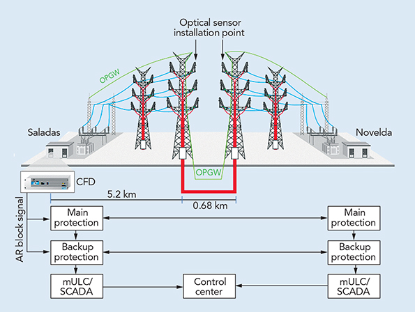
To address this issue, REE selected a technology developed by ARTECHE, which consists of a solution based on passive optical current sensors used to measure current and enhance the fault-detection scheme using the principle of current differential protection between both ends of the cable section. All installed sensors are managed by a single device—the Cable Fault Detection (CFD) signal processor—located at the nearest substation. The current sensors are connected to the CFD unit via standard single-mode optical fiber.
One of the main objectives of the project is to provide underground cable fault detection (CFD) functionality without altering the existing infrastructure or interfering with the current protection and control systems. Therefore, the system must be designed to optimize installation and minimize any impact on the existing equipment along the transmission line.
Proposed Solution
Current is measured using passive optical sensors based on the Faraday effect. The operating principle of the passive current sensor is a key aspect of the system. These sensors can be installed at the desired measurement point without requiring any power supply, unlike other types of current sensors such as Rogowski coils. This characteristic, combined with the fact that the connection between the sensors and the CFD unit is made using standard optical fibers, enables the deployment of a remote measurement system without the need for dedicated infrastructure.
Optical fibers from the existing OPGW cable are used to connect the sensors to the CFD unit. Since optical fibers within the OPGW are a limited resource, the system is designed to require only two fiber pairs to operate the entire setup. Additionally, to facilitate installation, splice boxes—commonly used by the TSO for OPGW installation—are employed to house the optical circuits and their associated fixing elements.
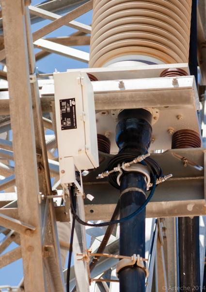
Each optical sensor includes a flexible sensing coil enclosed in an insulated cable, designed to wrap around the high-voltage cable just below the outdoor termination bushing at the transition point between the overhead line and the underground cable. The sensing coil must encircle both the high-voltage underground cable and the cable sheath grounding conductor. Since the sheath grounding conductor is also routed through the termination bushing, the system can detect faults both in the cable and in the termination bushing—locations where faults frequently occur in underground cable sections.
Another advantage of the passive remote current measurement system is that it does not require maintenance or recalibration after commissioning. Furthermore, the system continuously self-monitors the optical signal power levels across all fiber links, ensuring that any connection failure is immediately reported through the corresponding alarm contact.
With individual phase-current measurements obtained from the six installed sensors, the CFD unit executes a conventional differential protection algorithm. In the event of a fault occurring in the cable or in the outdoor termination bushing, the system will detect the fault and the CFD output will send a reclose-blocking signal to the protection relays installed for the overhead transmission line.
To deploy the entire system, the following equipment is required:
-
Six optical sensors, three at each transition point between the overhead line and the underground cable;
-
Two standard single-mode fiber pairs from the existing OPGW;
-
One signal-processing and fault-detection unit.
Factory Testing
The OMICRON CMC 356 device was used to inject test currents. The current output was combined with a current transformer acting as an amplifier to simulate real system faults up to 4000 A, as well as single-phase faults up to 6000 A. To reproduce the distance parameters of the line selected for the field test, two optical-fiber coils of 5.2 km (3.2 miles) and 6.2 km (3.9 miles) were used.
The output of the CFD unit sent signals to the binary input of the CMC 356 to emulate the reclose-blocking signal. For monitoring purposes, REE requested an additional output—a digital output providing the measured current values in the form of Sampled Values according to the IEC 61850-9-2LE process bus protocol.
Sensor Integration
The solution was developed to meet the requirements of REE’s R&D project, applying it to the 220 kV transmission line between Saladas and Novelda to enable coordinated protection and CFD functionality for mixed high-voltage lines. The distance between the Saladas substation and the far end of the underground cable section is 5.88 km (3.65 miles), with the underground cable itself being 680 m (2231 ft) long.
The current sensors were installed on towers 34 and 35 of the Saladas–Novelda transmission line, wrapped around the underground cable just below the termination bushing, without requiring any modifications to the tower structures. After installation, the corresponding optical fibers from the sensors were connected to the designated OPGW fiber pairs within the splice box.
The CFD unit, located at the Saladas substation, measures all current signals coming from the six installed sensors. Finally, the reclose-blocking signal from the CFD unit is connected to the line protection scheme. In the event of a fault on the underground cable, the line protection will detect the fault and initiate the auto-reclose cycle. At the same time, the CFD detects the fault and sends a signal to the line protection to stop the auto-reclosing sequence and issues a blocking signal to the logic control unit, which then reports the event to the control center.

Field Installation
The field installation work was completed over three days, with the following personnel and materials required:
-
Two technicians experienced in OPGW installation to perform fiber splicing and sensor installation;
-
A 40-meter tower crane to lift the line workers up to the cable termination bushing;
-
A standard fiber-optic splicing kit;
-
Standard tools for handling optical fibers and carrying out OPGW installation.
No equipment was required to supply power at the measurement points, and the circuit remained energized during installation. Moreover, no setting changes, field adjustments, or modifications to REE’s existing protection and control systems were necessary.
Although the selected overhead transmission line used for the field test included only a single underground cable section, this protection scheme can be applied to overhead high-voltage circuits containing multiple underground cable sections.

To date, no cable fault has occurred on the 220 kV circuit, so the newly installed protection system has not yet operated in a real event. However, to validate its performance, REE will soon install an independent external disturbance recorder, connecting it to the digital output of the CFD unit. This recorder will be compatible with the IEC 61850-9-2LE process bus protocol as well as conventional protection interfaces, enabling comparable results to be obtained when an external fault occurs on the underground cable.
Future Optimization
The main objective of the system is to ensure maximum reliability of the line protection scheme. However, it has also been designed with a focus on optimizing the required installation equipment, aligning with existing infrastructure, significantly reducing costs, simplifying the installation process, and shortening commissioning time. Furthermore, the system requires no operational work or maintenance, which enhances its long-term cost-effectiveness. The outcome of this R&D project is a system that provides full reliability and seamless integration at minimal cost.
The optical current-sensing technology enables improved grid protection capabilities. However, REE has identified an outstanding challenge: locating the exact fault position within the underground cable. In fact, this has become an additional requirement to allow REE to obtain accurate information on cable fault locations, thereby facilitating optimal restoration of the line.
REE’s long-term goal is to replace distance protection with a new technology capable of detecting underground cable faults directly. REE is currently testing a similar solution from another supplier to compare with ARTECHE’s technology before establishing a new standard. For underground cables installed prior to the adoption of integrated optical fibers, retrofitting this protection scheme on all existing mixed high-voltage lines will present difficulties.
Acknowledgment
This project was carried out as part of an R&D initiative promoted by REE. The author acknowledges the technical support provided by ARTECHE in developing the technology and in preparing this article.
About the Author
Francisco Javier Martin Herrera (fjmartin@ree.es) received his BSEE degree from Universidad Carlos III de Madrid in 2001 and joined Red Eléctrica de España in 2002. He has worked extensively on protection coordination in the Spanish high-voltage power system and is currently involved in protection studies for the INELFE project and the HVDC interconnection between France and Spain. He has participated in CIGRE B5 working groups on shunt reactor protection and is a member of CENELEC CLC/TC 8X on the same subject. In addition, Martin Herrera is a lecturer in electrical engineering at Pontificia Comillas University – ICAI in Madrid, where he teaches power system protection.
Mentioned in the Article
-
ARTECHE | www.arteche.com
-
OMICRON | www.omicron.at
-
Red Eléctrica de España (REE) | www.ree.es